
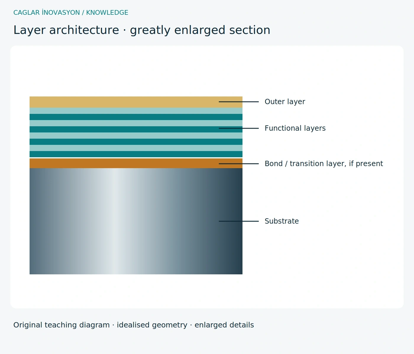
Layer architecture starts with the substrate
The substrate supports the cutting forces. A suitable clean interface connects it to the coating; a separate bond layer is not present in every system. Functional layers can influence abrasion, heat transfer and adhesion. The drawing greatly exaggerates layer thickness and does not prescribe a universal coating recipe.
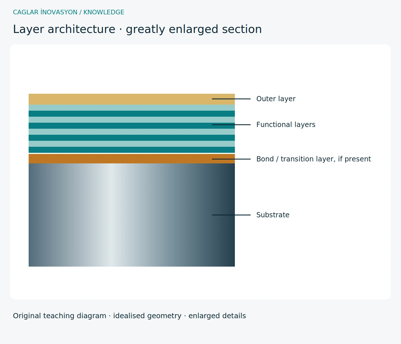
PVD and CVD: match the process to the tool
PVD deposits material from a physically generated vapour, for example by arc evaporation or sputtering. CVD grows coatings through chemical reactions of gaseous precursors. PVD often enables thin coatings on sharp drills, end mills and threading tools. CVD systems combining TiCN and alumina are also used on heavily loaded indexable inserts. Process temperature, edge preparation and substrate compatibility constrain selection; neither process is universally better.
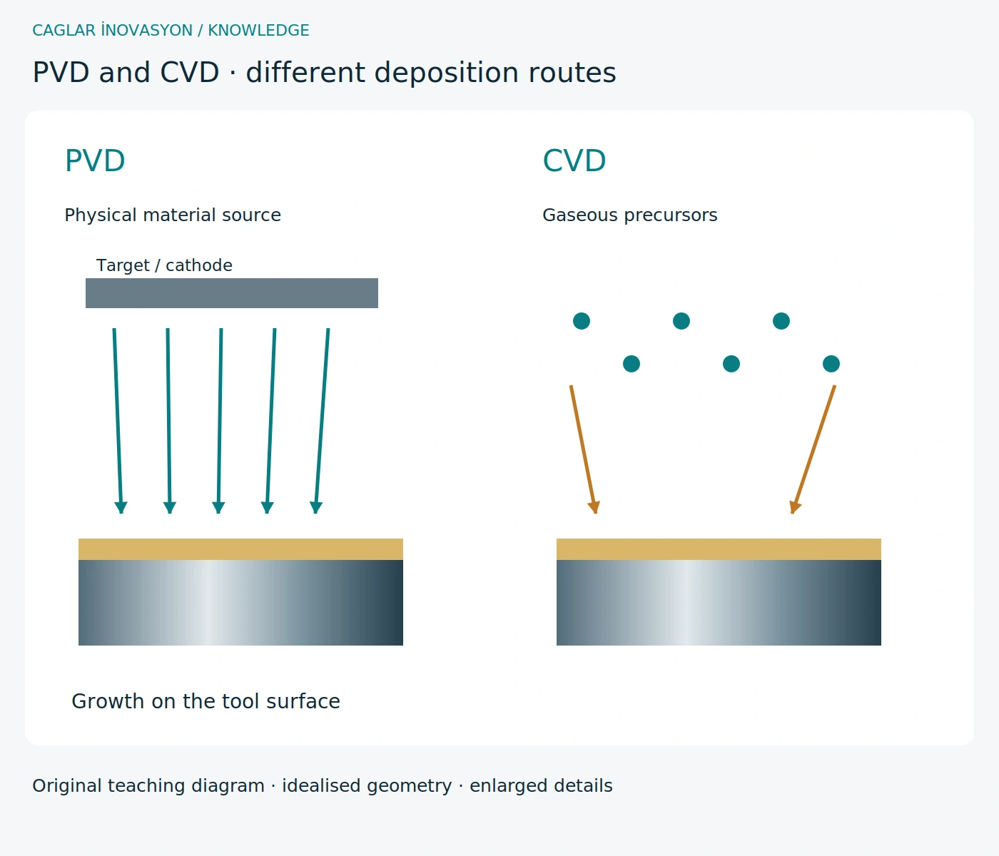
Droplets and their effect on the surface
A cathodic arc can eject liquid metal droplets from the target along with the coating flux. Embedded or adhering particles create protrusions; detachment can leave defects. Depending on size and application, they influence roughness, local contact, friction and chip sliding. Optimised arc control, filtering concepts or suitable sputtering processes reduce these particles. Controlled post-treatment can smooth peaks but cannot replace sound adhesion. Droplet density is not identical in all PVD coatings.
Multilayers and nanolaminates: engineered interfaces
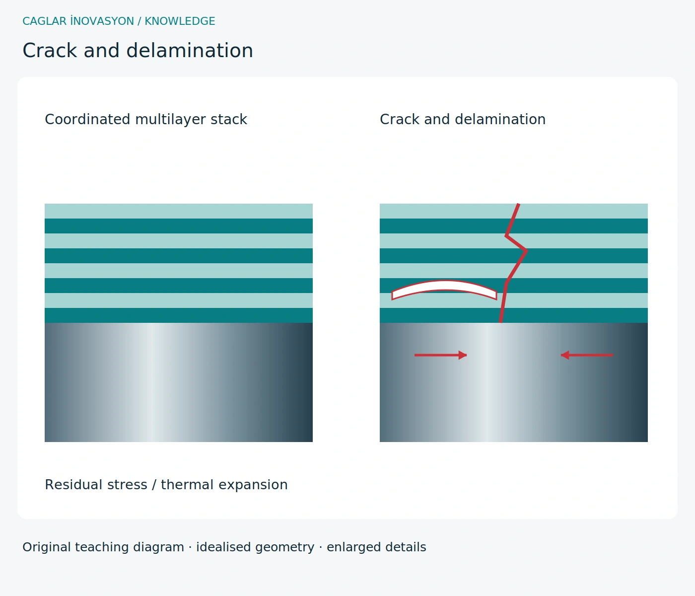
Coordinated layers can combine functions and impede crack propagation. Nanolaminates use repeated very thin layers; performance does not follow from layer count alone. Each additional interface requires suitable bonding. Thermal expansion mismatch, residual stress and unsuitable total thickness can promote cracking or delamination. The diagram separates an intentional multilayer architecture from a damaged stack.
Recoating is more than adding another layer
Regrinding, residual coating, contamination and edge preparation determine the next process. Check whether stripping is required and compatible with the substrate before recoating. Uncontrolled build-up changes diameter, edge radius and thread profile; new layers do not eliminate underlying damage. The reconditioner must assess geometry, adhesion and permitted cycles. Greater total thickness does not guarantee longer tool life.
Four applications, four selection checks
Milling needs resistance to fluctuating loads and temperatures as well as abrasion. Drilling demands suitable chip space, edge condition and lubrication. In turning, a suitable CVD alumina layer can limit heat transfer. Tapping requires sharp geometry, correct profile dimensions and controlled friction; form tapping adds high contact pressure. Document comparative trials with the same geometry and substrate. A coating name alone cannot explain a tool-life difference.
Select a coating: no universal winner
The table gives selection directions, not guaranteed product data. Hardness, hot performance, oxidation, friction, adhesion and thickness depend on the actual system. Supplier specifications and trials in the actual material take precedence over colours or brand names.
| System | Possible application | Limits |
|---|---|---|
| TiN | Versatile reference, for example on HSS tools | Not universal protection at very high temperatures |
| TiCN | Abrasion resistance, for example in tapping | Account for temperature and lubrication |
| TiAlN / AlTiN | Hot and oxidation performance in suitable milling and drilling | Aluminium content and structure matter; not a blanket choice for aluminium parts |
| AlCrN | Thermally loaded milling and gear tools, system dependent | Check bonding, edge preparation and cooling |
| Al₂O₃ | Thermally and chemically resistant layer, often in CVD turning inserts | Consider brittleness and the complete grade in interrupted cuts |
| DLC | Low-friction, low-adhesion surfaces for suitable non-ferrous applications | Amorphous carbon is not crystalline diamond; check thermal limits |
| Diamond | Abrasive non-ferrous and composite materials with a suitable substrate | Usually unsuitable for hot steel cutting; check bonding and edge radius |
Benefits and limitations
A suitable coating may improve life but adds cost and works together with edge preparation. A sharp uncoated tool can outperform an unsuitable coating in the right application.
Practical example · not a customer performance claim
Example: compare two coated end mills. If carbide, geometry and edge rounding also change, a life difference cannot be attributed to coating alone. Keep these factors as comparable as possible.
Comparing alternatives
For regrinding, clarify which surfaces are recoated and whether geometry and size still suit the application. A colour change alone does not prove a quality defect.
Common problems, causes and remedies
These steps are a diagnostic workflow, not a confirmed remote diagnosis. Retest under controlled conditions after a change.
| Step | Check and action |
|---|---|
| Recognise | Flaking or rapid built-up edge |
| Possible causes | Overload, adhesion, unsuitable layer system or preparation |
| Isolate systematically | Record damage location/time; compare application range and original edge |
| Corrective action | Check mechanical causes first; trial a suitable substrate/coating/geometry system |
| Prevent recurrence | Keep trials comparable and define reconditioning requirements |
Problem – cause – action at a glance
Use the diagnostic checks above before taking action. One symptom does not prove one specific cause.
| Problem | Possible cause | Recommended action |
|---|---|---|
| Flaking or rapid built-up edge | Overload, adhesion, unsuitable layer system or preparation | Check mechanical causes first; trial a suitable substrate/coating/geometry system |