
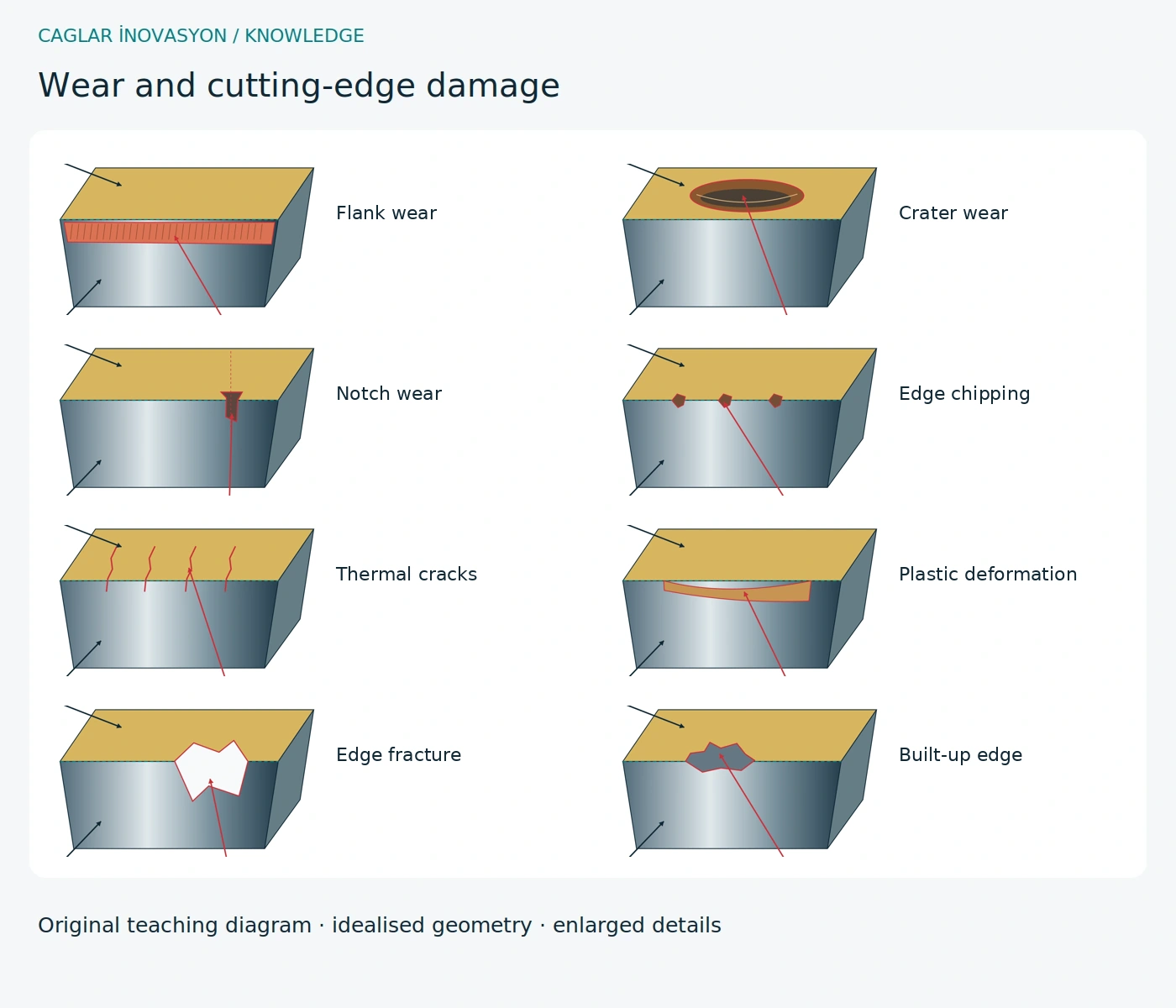
Appearance, mechanism or damage?
Appearance describes the visible position and shape. Abrasion removes material mechanically; adhesion starts with sticking and may pull material away on separation. Diffusion changes the interface through material transport when temperature and the material pair permit it. Oxidation is reaction with oxygen. Mechanical overload and thermal cycling also cause cracks or fracture. Several processes may overlap; a photograph alone cannot establish a definitive cause.
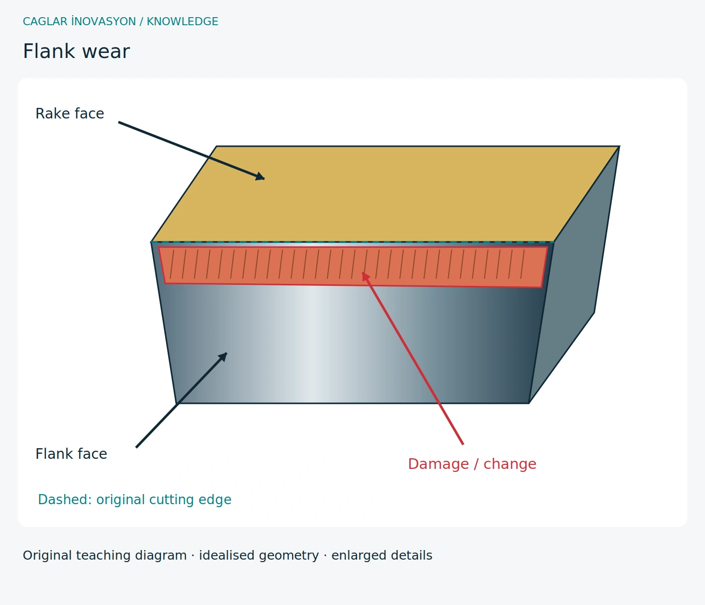
Flank wear
Appearance and causes: A growing wear land appears on the clearance face below the cutting edge. Friction and abrasive particles contribute.
Possible consequences: Dimensional drift, rising forces and declining finish may indicate a progressive, manageable end of tool life.
Checks and actions: Measure the wear land periodically and define a replacement limit; review cutting speed and a more wear-resistant grade with the supplier.
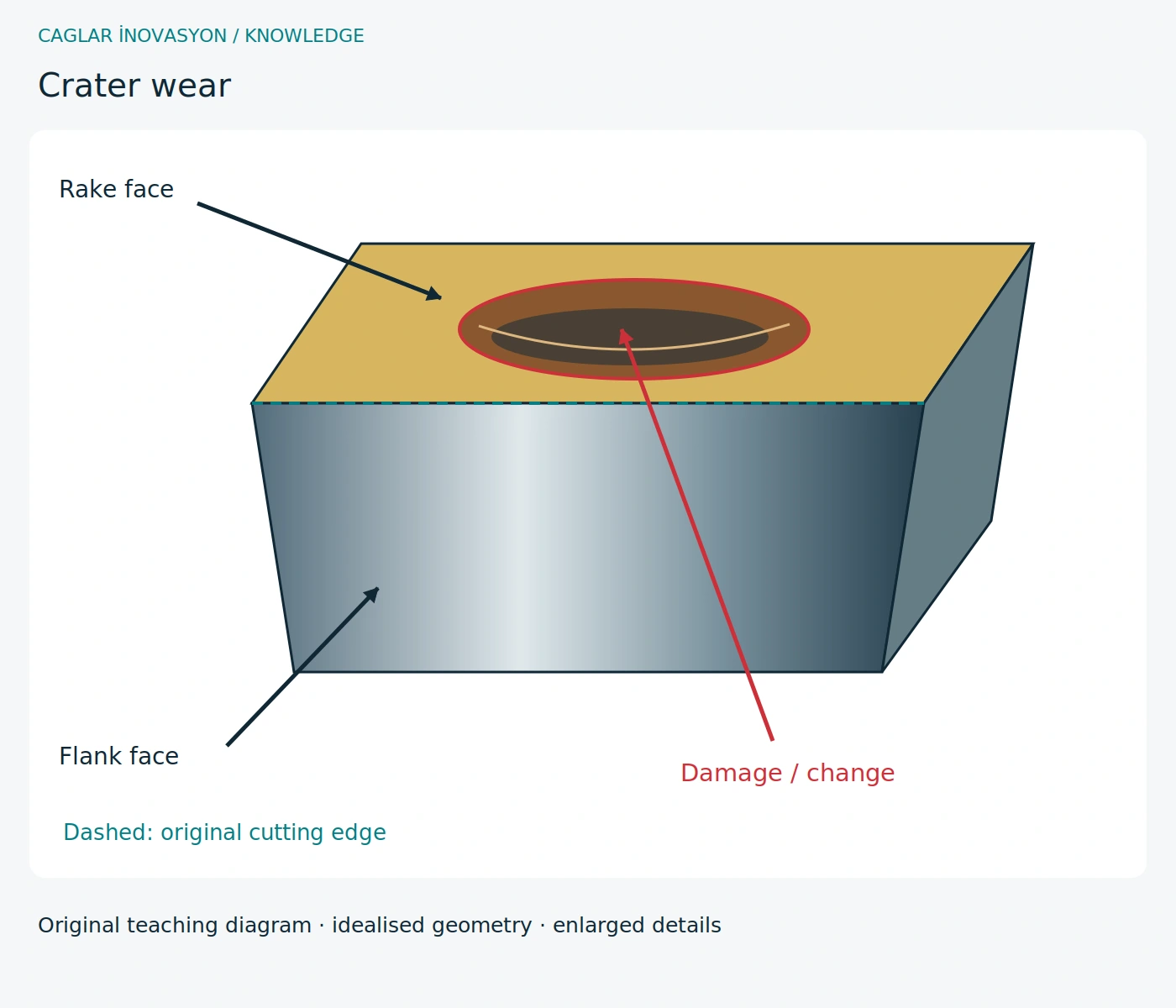
Crater wear
Appearance and causes: A depression develops on the rake face where the chip slides. Abrasion and temperature-dependent chemical processes can act together.
Possible consequences: A deep crater weakens the remaining wedge and may ultimately cause fracture.
Checks and actions: Reduce thermal load through suitable cutting data; review coating and chip flow. Replace before the crater breaks through.
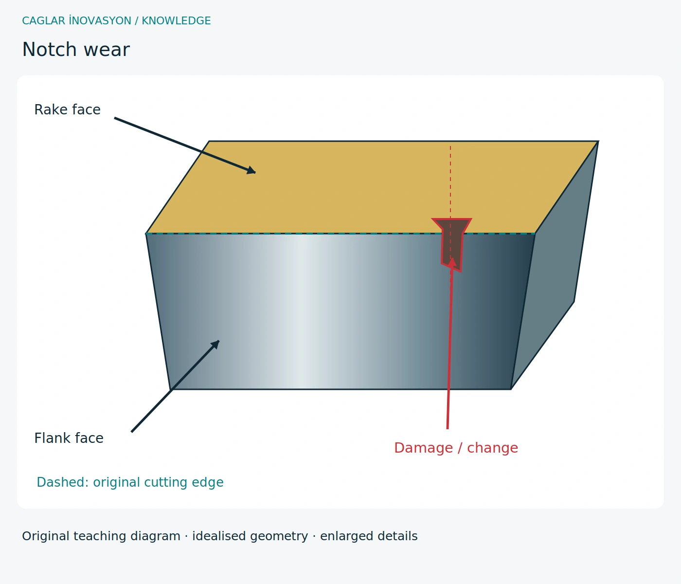
Notch wear
Appearance and causes: Local damage concentrates at the depth-of-cut line, for example near a hardened surface, scale or adhesive contact.
Possible consequences: A single notch can cause burrs, dimensional errors and eventual fracture.
Checks and actions: Check surface condition and engagement; vary depth where permitted and select suitable geometry and grade.
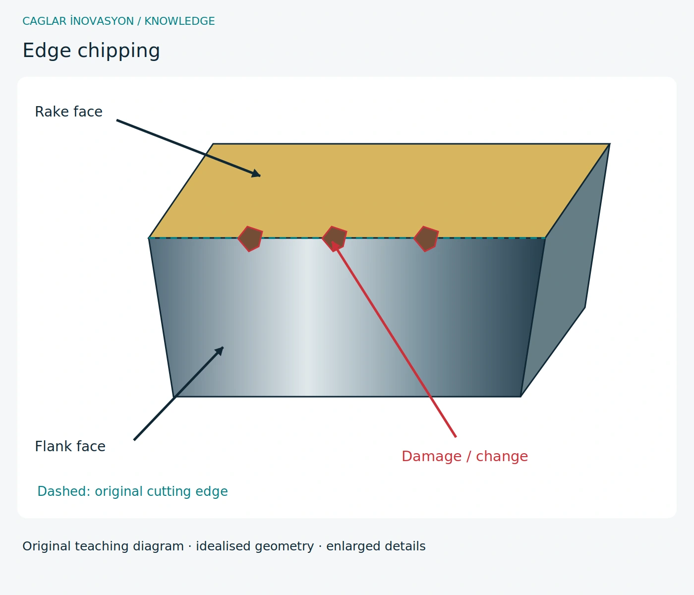
Edge chipping
Appearance and causes: Small fragments are missing from the edge. Vibration, chip impact, hard inclusions or a fragile edge can initiate damage.
Possible consequences: Irregular marks and a sudden loss of finish replace a gradual wear pattern.
Checks and actions: Check clamping, runout and chip evacuation first; test a stronger edge or tougher grade and avoid abrupt entry.
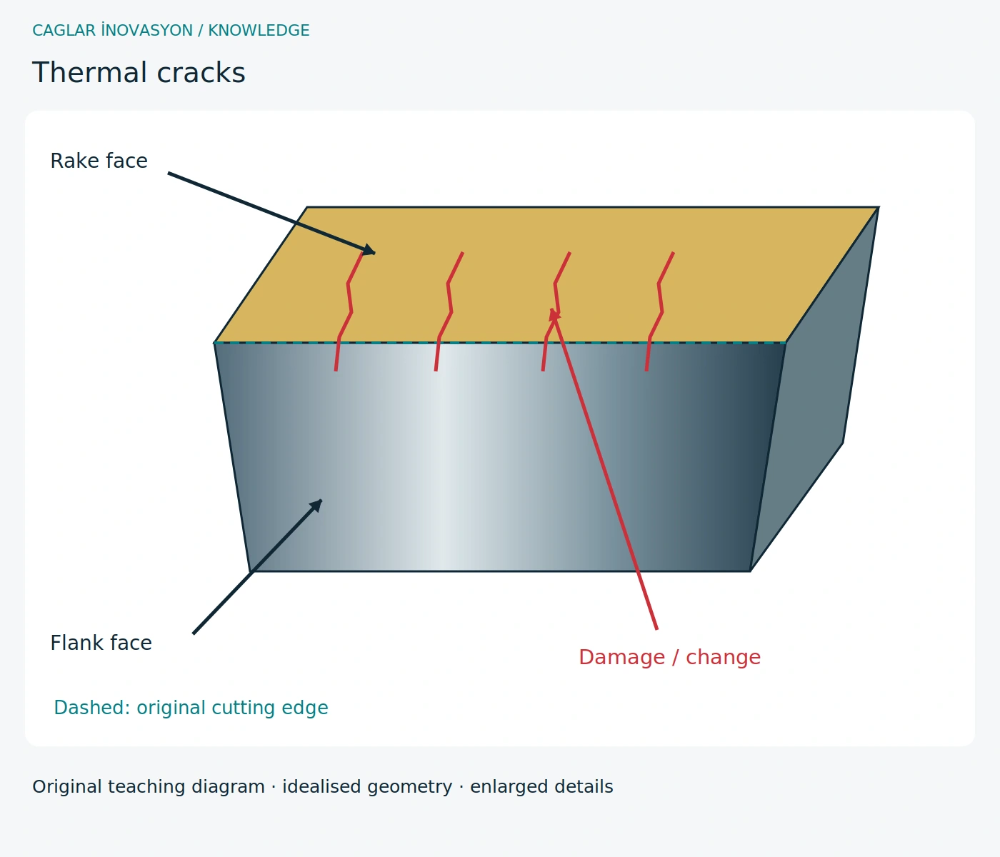
Thermal cracks
Appearance and causes: Several cracks run approximately across the cutting edge. Repeated heating and cooling particularly affect interrupted cutting.
Possible consequences: Cracks may grow into chipping. Distinguish a single thermal shock from repeated thermal cycling.
Checks and actions: Maintain a consistent, supplier-approved cooling strategy and select a suitable grade. Dry cutting is not a universal remedy.
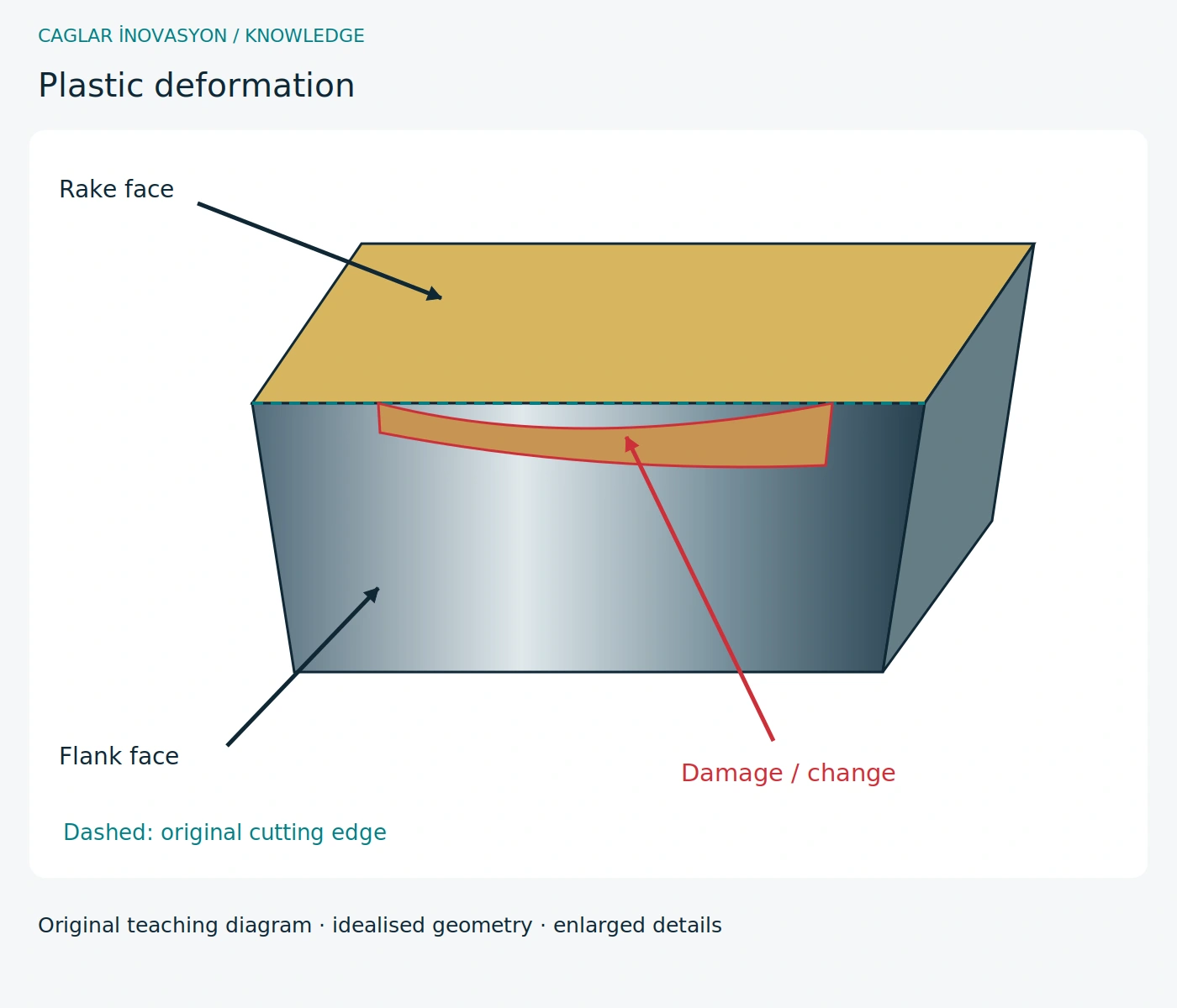
Plastic deformation
Appearance and causes: Heat and pressure permanently displace the edge. The original wedge geometry is no longer retained.
Possible consequences: Profile changes, friction and dimensional errors may progress to breakage.
Checks and actions: Reduce thermal and mechanical loading; choose greater hot strength and adequate edge support.
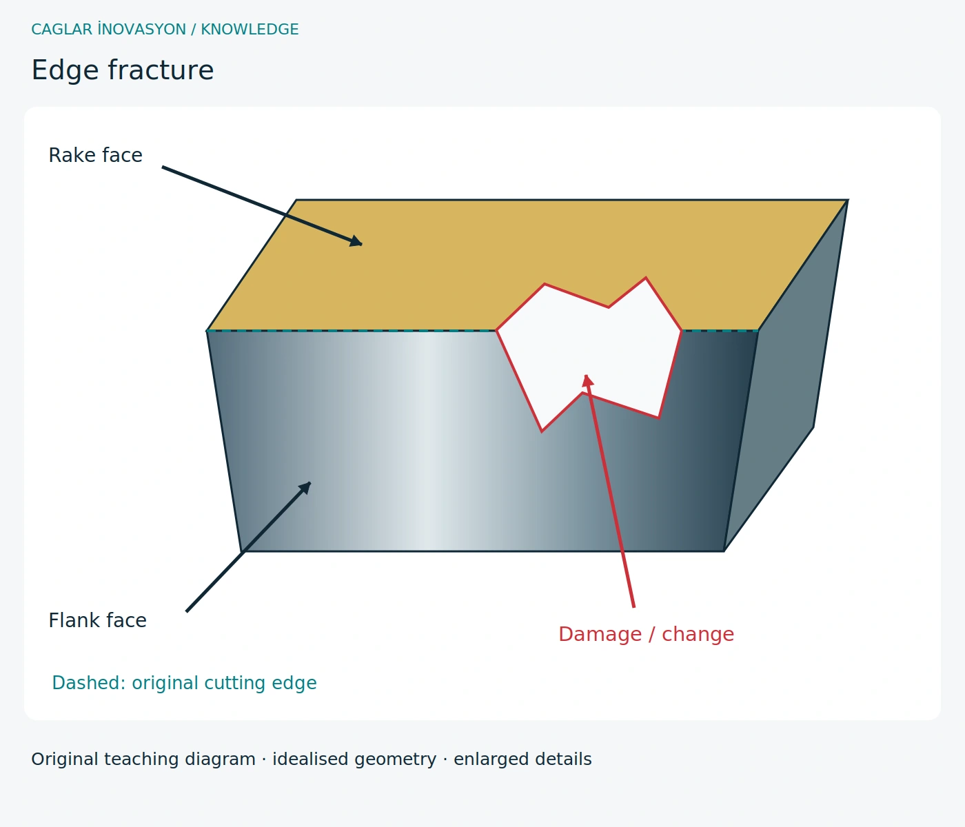
Edge fracture
Appearance and causes: A substantial section of the edge is missing. Overload, collision or accumulated earlier damage may be responsible.
Possible consequences: Sudden failure can damage the part and subsequent tools.
Checks and actions: Stop the process, remove fragments and investigate; check toolpath, clamping and loading before restarting.
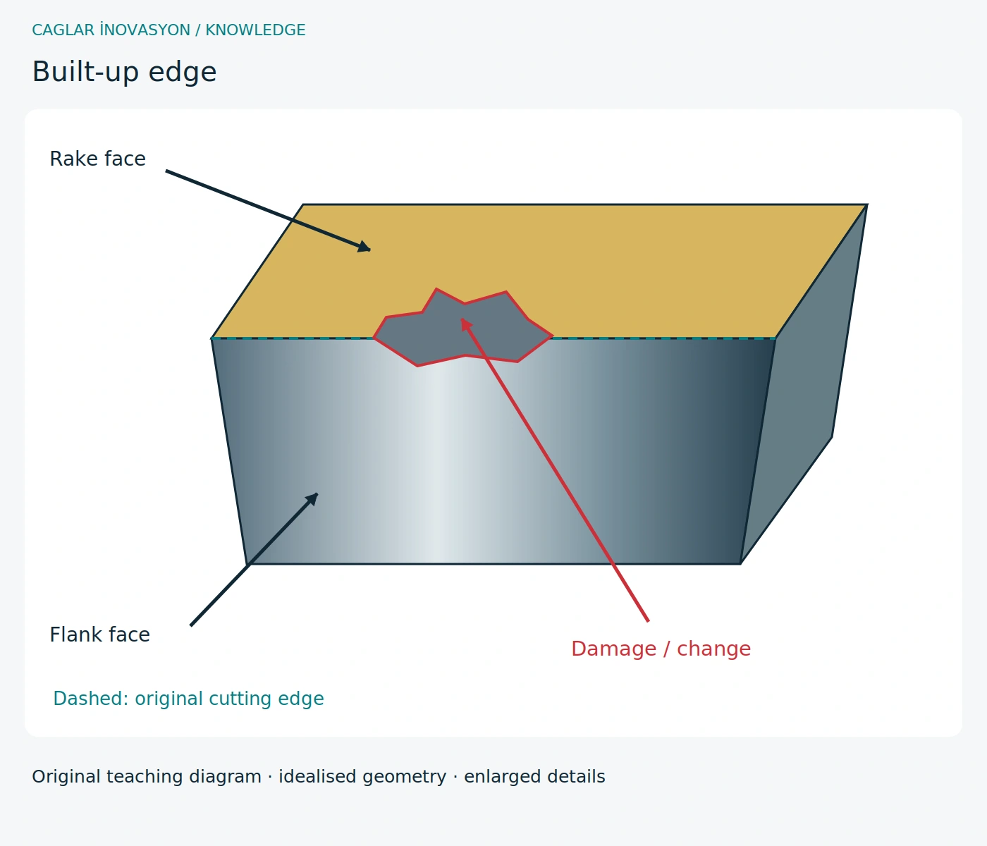
Built-up edge
Appearance and causes: Workpiece material adheres to the cutting edge and changes its effective geometry. This is deposited material, not simply loss of tool material.
Possible consequences: Repeated build-up and detachment can smear surfaces, change dimensions and tear out cutting material.
Checks and actions: Check lubrication, rake-face condition and material-specific geometry; adjust speed only within approved limits.
Comparison and actions
Investigate first, then change one relevant variable. Damage patterns can overlap.
| Damage pattern | Possible cause / signs | Effect | Remedy and prevention |
|---|---|---|---|
| Flank wear | A growing wear land appears on the clearance face below the cutting edge. Friction and abrasive particles contribute. | Dimensional drift, rising forces and declining finish may indicate a progressive, manageable end of tool life. | Measure the wear land periodically and define a replacement limit; review cutting speed and a more wear-resistant grade with the supplier. |
| Crater wear | A depression develops on the rake face where the chip slides. Abrasion and temperature-dependent chemical processes can act together. | A deep crater weakens the remaining wedge and may ultimately cause fracture. | Reduce thermal load through suitable cutting data; review coating and chip flow. Replace before the crater breaks through. |
| Notch wear | Local damage concentrates at the depth-of-cut line, for example near a hardened surface, scale or adhesive contact. | A single notch can cause burrs, dimensional errors and eventual fracture. | Check surface condition and engagement; vary depth where permitted and select suitable geometry and grade. |
| Edge chipping | Small fragments are missing from the edge. Vibration, chip impact, hard inclusions or a fragile edge can initiate damage. | Irregular marks and a sudden loss of finish replace a gradual wear pattern. | Check clamping, runout and chip evacuation first; test a stronger edge or tougher grade and avoid abrupt entry. |
| Thermal cracks | Several cracks run approximately across the cutting edge. Repeated heating and cooling particularly affect interrupted cutting. | Cracks may grow into chipping. Distinguish a single thermal shock from repeated thermal cycling. | Maintain a consistent, supplier-approved cooling strategy and select a suitable grade. Dry cutting is not a universal remedy. |
| Plastic deformation | Heat and pressure permanently displace the edge. The original wedge geometry is no longer retained. | Profile changes, friction and dimensional errors may progress to breakage. | Reduce thermal and mechanical loading; choose greater hot strength and adequate edge support. |
| Edge fracture | A substantial section of the edge is missing. Overload, collision or accumulated earlier damage may be responsible. | Sudden failure can damage the part and subsequent tools. | Stop the process, remove fragments and investigate; check toolpath, clamping and loading before restarting. |
| Built-up edge | Workpiece material adheres to the cutting edge and changes its effective geometry. This is deposited material, not simply loss of tool material. | Repeated build-up and detachment can smear surfaces, change dimensions and tear out cutting material. | Check lubrication, rake-face condition and material-specific geometry; adjust speed only within approved limits. |
Benefits and limitations
Wear monitoring supports planned replacement before dimensional errors or breakage. It needs inspection time and comparable images; one damage pattern rarely proves one cause.
Practical example · not a customer performance claim
Example: a turning process develops dimensional drift and a growing flank land. Record tool and measurements at equal part counts. Derive replacement intervals from quality limits and variation, not an invented universal wear threshold.
Comparing alternatives
Longer life is not always cheaper than an earlier planned change. Include scrap risk and change cost. Treat notches and cracks separately from uniform wear.
Common problems, causes and remedies
These steps are a diagnostic workflow, not a confirmed remote diagnosis. Retest under controlled conditions after a change.
| Step | Check and action |
|---|---|
| Recognise | Sudden chipping after stable running |
| Possible causes | Chip recutting, collision, changing engagement or advanced wear |
| Isolate systematically | Align last good part, tool image and program step; do not reuse the damaged edge |
| Corrective action | Remove the cause, inspect replacement tooling and perform a supervised first run |
| Prevent recurrence | Introduce defined inspection, chip evacuation and recorded life criteria |
Problem – cause – action at a glance
Use the diagnostic checks above before taking action. One symptom does not prove one specific cause.
| Problem | Possible cause | Recommended action |
|---|---|---|
| Sudden chipping after stable running | Chip recutting, collision, changing engagement or advanced wear | Remove the cause, inspect replacement tooling and perform a supervised first run |