
Basic principle
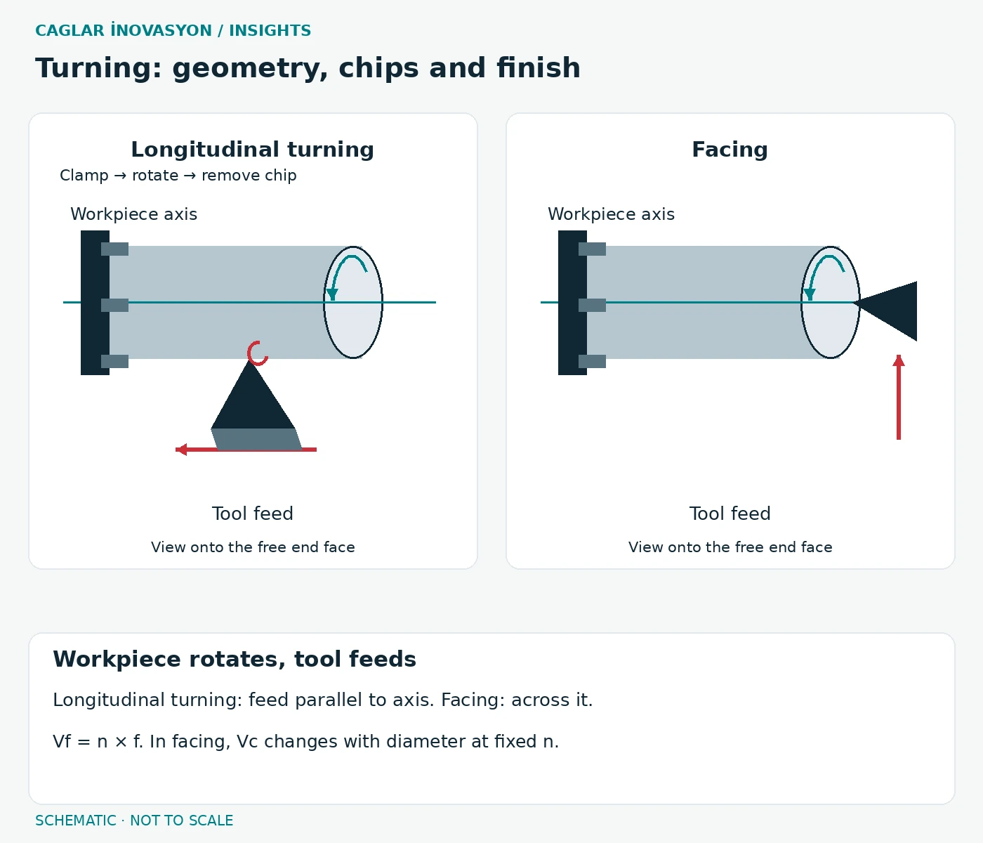
In conventional turning the workpiece rotates while the edge follows the required contour. Longitudinal feed runs parallel to the axis; facing feed runs across it. Grooving requires suitable tool width and clearance.
Key relationships
Feed per revolution, depth, nose radius and chipbreaker must work together. A larger nose radius is not a universal route to a better finish: on a compliant setup the resulting forces may encourage vibration.
Selection and limitations
At constant spindle speed, cutting speed changes with diameter. Conditions near the centre therefore deserve particular attention during facing. Constant surface speed requires a suitable spindle-speed limit and compliance with workholding limits.
Practical checks
For process assessment, provide diameter range, material condition, insert, holder, overhang and actual cutting data. Record long chips, dimensional changes and chipped edges separately. Observe chip formation only with protective guarding closed.
Benefits and limitations
Turning suits shafts, bushes and rotational contours. A stable continuous cut can be predictable; long overhang, slender parts and interrupted cuts constrain the parameters.
Practical example · not a customer performance claim
Example: diameter changes along a long shaft. Check elastic deflection before applying a tool offset. Suitable support and a separate finishing pass may address the cause better than a blanket correction.
Comparing alternatives
Internal turning needs stiff boring bars. Milling may complement turning for non-rotational features. Grooving geometry prevents direct transfer of general longitudinal-turning values.
Common problems, causes and remedies
These steps are a diagnostic workflow, not a confirmed remote diagnosis. Retest under controlled conditions after a change.
| Step | Check and action |
|---|---|
| Recognise | Tapered diameter or chatter |
| Possible causes | Part deflection, alignment, overhang, edge wear |
| Isolate systematically | Measure along the length; compare cold/warm states and edge condition |
| Corrective action | Check support and alignment; reduce overhang; trial a defined finishing allowance |
| Prevent recurrence | Define inspection locations and temperature condition; record offsets |
Problem – cause – action at a glance
Use the diagnostic checks above before taking action. One symptom does not prove one specific cause.
| Problem | Possible cause | Recommended action |
|---|---|---|
| Tapered diameter or chatter | Part deflection, alignment, overhang, edge wear | Check support and alignment; reduce overhang; trial a defined finishing allowance |