
How it works
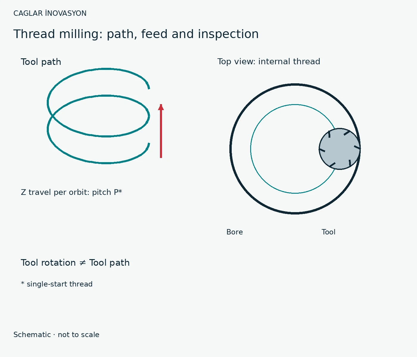
The cutter rotates about its own axis while travelling around the thread axis. For a single-start thread, Z displacement per orbit equals the pitch. The control must interpolate the axes simultaneously.
Selection and requirements
Check tool profile, pitch, cutting length, pilot-hole diameter and collision clearance. A cutter is not automatically suitable for every thread size or profile.
Benefits and limits
Path compensation allows thread-size adjustment. The tool is smaller than the bore and can be an alternative where a trapped or broken tap is costly. It needs appropriate programming, clearance and verified entry/exit paths.
Technical relationships
For internal threads, the tool centre travels a smaller circle than the contact point. Circumferential feed and programmed centre-path feed are therefore different. Use the manufacturer or CAM correction for the actual geometry. The general cutting calculator does not yet include this path correction.
Practical example
Hypothetical example: an expensive housing needs a blind thread close to its floor. Compare tapping with thread milling. Simulate entry, depth, floor clearance and exit, then inspect a trial part using a suitable gauge.
Alternatives and checks
Tapping is often simpler and faster in a suitable application. Form tapping needs sufficient ductility and a matching pilot hole. Material, profile, quantity and scrap risk determine the choice.
Problems – causes – remedies
Possible causes only: observe and isolate first, change one factor and verify. Record effective measures as process standards.
| Problem | Possible cause | Check / remedy |
|---|---|---|
| Thread outside tolerance | Tool size, runout or path correction | Verify size and gauge, adjust compensation deliberately and remeasure a trial part. |
| Chatter / chipping | Overhang, engagement or chip recutting | Check clamping and runout; correct engagement, path and evacuation using tool guidance. |