
Basic principle
Milling uses successive cutting edges on a rotating tool. Faces, shoulders and slots impose different demands. Define the contour, access and required finish before selecting the cutter and machining strategy.
Key relationships
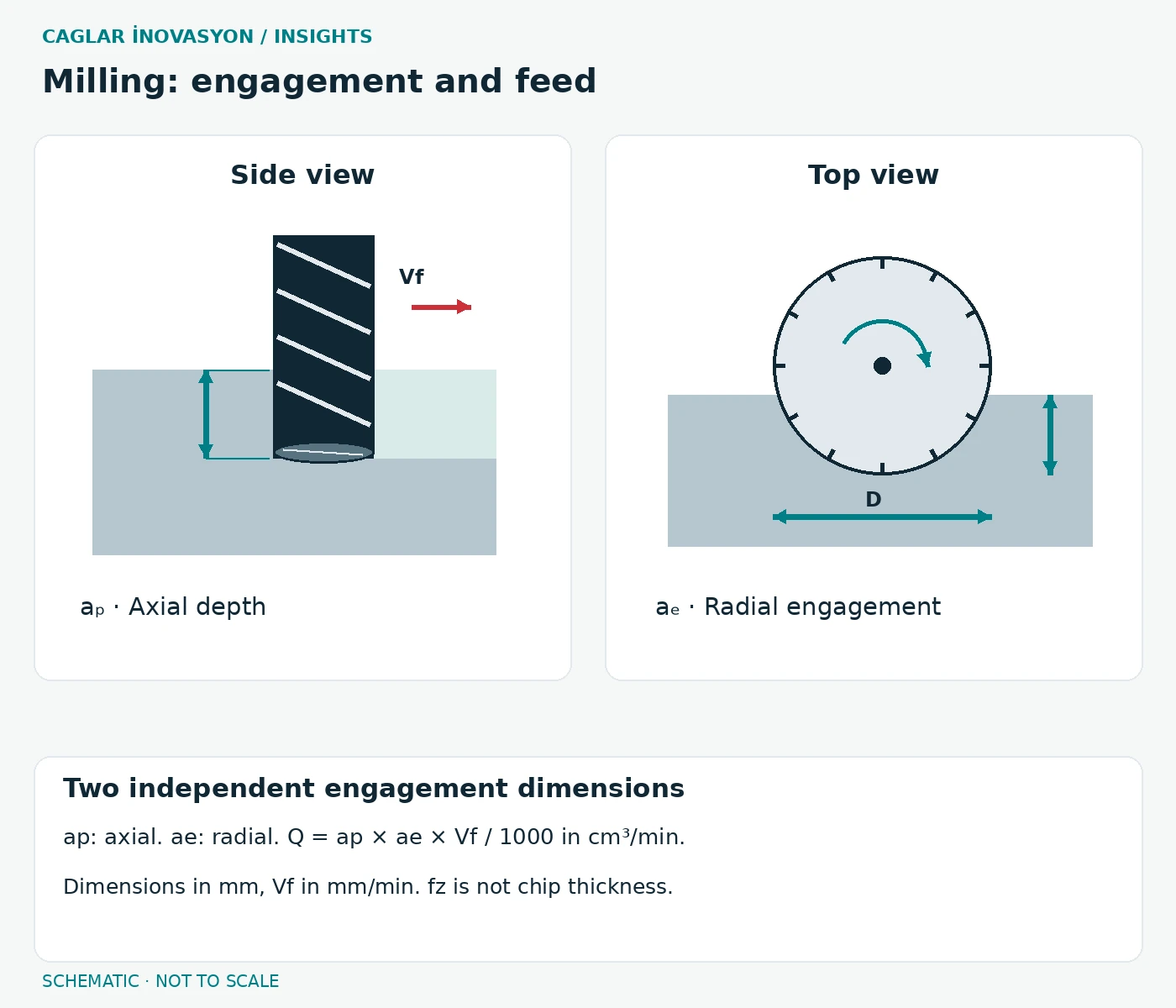
Axial depth aₚ and radial engagement aₑ describe different dimensions of the cut. Feed per tooth fz is not the actual chip thickness: engagement and geometry also influence that thickness.
Selection and limitations
The basic feed relationship is vf = n × z × fz: spindle speed n in min⁻¹, effective tooth count z, feed per tooth in mm and feed speed in mm/min. Calculation example, not a recommendation: 3,000 × 4 × 0.04 = 480 mm/min. Obtain permissible values from the specific tool data.
Practical checks
When chatter occurs, examine overhang, holder, workholding and changes in engagement first. A corner can substantially change tool loading. Make traceable individual changes during trials and record finish, tool life and machining time.
Benefits and limitations
Milling produces flat and three-dimensional contours. Reach and productivity compete: a slender long tool reaches deeper features but is less stiff. More teeth do not automatically permit more usable feed.
Practical example · not a customer performance claim
Example: rough a pocket in an aluminium plate, then finish wall and floor with defined allowance. This separates removal rate from finish requirements without guaranteeing a tolerance.
Comparing alternatives
An open face may justify a face mill, while a narrow pocket needs a smaller diameter. Turning may be more economical for rotational surfaces.
Common problems, causes and remedies
These steps are a diagnostic workflow, not a confirmed remote diagnosis. Retest under controlled conditions after a change.
| Step | Check and action |
|---|---|
| Recognise | Poor finish or exit burr |
| Possible causes | Runout, worn edge, unfavourable exit, recut chips |
| Isolate systematically | Compare individual edges, inspect holder and workpiece, locate burrs against the path |
| Corrective action | Replace damaged tooling; improve exit and chip evacuation; evaluate a separate finish pass |
| Prevent recurrence | Define runout checks, replacement criteria and a deburring-aware sequence |
Problem – cause – action at a glance
Use the diagnostic checks above before taking action. One symptom does not prove one specific cause.
| Problem | Possible cause | Recommended action |
|---|---|---|
| Poor finish or exit burr | Runout, worn edge, unfavourable exit, recut chips | Replace damaged tooling; improve exit and chip evacuation; evaluate a separate finish pass |